Leave Your Message

How to Understand Transformer Definition in 2026?

By 2026, Transformer Definition most often describes an AI model that processes relationships between parts of a sequence. The same word also names an electrical device that changes voltage. Context matters. This guide focuses on the AI meaning and flags where the terminology can confuse beginners.

The original research offers a useful anchor. Ashish Vaswani and his coauthors wrote, “We propose a new simple network architecture, the Transformer, based solely on attention mechanisms.” Their 2017 paper, “Attention Is All You Need,” introduced the architecture. In practice, attention helps a model weigh connections between tokens, such as words in a sentence. Picture a system examining “bank” beside “river” rather than treating every word in isolation. That example is simplified, but it shows why context matters.

A clear definition should explain more than a name. It should distinguish tokens, attention, training, and the model’s actual task. Some explanations make Transformers sound almost human. They are not. They detect patterns from data, and their answers can still be wrong. The concept can feel slippery at first. That is normal. This introduction sets up a practical look at how Transformers work, where the definition applies, and what it does not promise.

How to Understand Transformer Definition in 2026?

What a Transformer Means in Electrical Engineering

How to Understand Transformer Definition in 2026?
What a Transformer Means in Electrical Engineering

In electrical engineering, a transformer transfers electrical energy between circuits through electromagnetic induction. It usually has two or more windings around a shared magnetic core. Alternating current in the primary winding creates a changing magnetic field. That field induces voltage in the secondary winding. No moving parts are required. The basic idea is simple.

The number of turns in each winding helps determine the voltage change. A winding with more turns generally has a higher voltage. In an ideal transformer, increasing voltage reduces current proportionally, while power remains constant. Real devices are less tidy. Copper resistance and heat in the core cause losses, so input power exceeds useful output.

Consider a small transformer inside a power supply: its core may fit in your hand, yet it can help adapt a higher input voltage for a lower-voltage circuit. Its rating, cooling, insulation, and operating frequency matter. A definition alone does not tell you whether a particular transformer is suitable. That takes careful checks. Even familiar calculations can miss practical details, such as temperature rise or load changes.

How to Understand Transformer Definition in 2026? — What a Transformer Means in Electrical Engineering

Concept What It Means Key Engineering Detail
Definition A transformer is a static electrical device that transfers energy between circuits through electromagnetic induction. It commonly changes AC voltage and current levels without changing the supply frequency.
Operating principle Alternating current in the primary winding creates a changing magnetic flux in the core, which induces voltage in the secondary winding. Electromagnetic induction requires changing magnetic flux; an ordinary transformer does not operate from steady DC alone.
Primary winding The winding connected to the electrical source. Its number of turns is represented by Np.
Secondary winding The winding connected to the load or output circuit. Its number of turns is represented by Ns.
Voltage ratio For an ideal transformer, the voltage ratio is proportional to the winding-turns ratio. Vs / Vp = Ns / Np. A higher secondary turns count generally gives a higher secondary voltage.
Current relationship For an ideal transformer, current changes inversely with the turns ratio. Is / Ip = Np / Ns. A voltage increase corresponds to a current decrease for approximately the same power.
Power and efficiency A transformer transfers electrical power; it does not create energy. Real output power is lower than input power because of winding, core, and other losses. Efficiency is output power divided by input power.
Magnetic core The core provides a magnetic path that links the windings. Many power transformers use laminated electrical steel to reduce eddy-current losses; some designs use other magnetic materials.
Step-up transformer Raises the secondary voltage relative to the primary voltage. Typically, Ns > Np; used where higher voltage is needed, such as in power transmission systems.
Step-down transformer Lowers the secondary voltage relative to the primary voltage. Typically, Ns < Np; used to provide lower voltages for distribution and equipment.
Isolation transformer Transfers energy while providing electrical separation between primary and secondary circuits. In a typical isolated design, the windings are not electrically connected to each other; isolation does not by itself guarantee safety.
Frequency The output frequency matches the input frequency in a conventional transformer. A transformer changes voltage and current relationships, not frequency.
Common applications Voltage conversion, electrical isolation, measurement, and power distribution. Examples include utility substations, distribution networks, chargers, and instrument transformers.
Typical losses Energy is lost mainly as heat in the windings and magnetic core. Winding resistance causes copper losses; hysteresis and eddy currents contribute to core losses.

How Electromagnetic Induction Transfers Electrical Energy

How to Understand Transformer Definition in 2026?

A transformer transfers electrical energy between circuits through electromagnetic induction. Its primary and secondary windings share a magnetic core, but their wires usually remain electrically separate. When alternating current flows through the primary winding, it creates a changing magnetic field in the core. That changing field links with the secondary winding and induces a voltage there. Not magic. The energy crosses through the magnetic field, not through electrons jumping between coils. A useful definition should describe this changing-flux process, not just call a transformer a voltage-changing device.

The voltage relationship depends mainly on the number of turns in each winding. If the secondary has more turns, its voltage is generally higher, while its current capacity decreases for similar input power. A small classroom transformer makes this visible: connect a low-voltage alternating supply, then measure the output with a meter. Use suitable equipment and follow its safety instructions. The ideal diagram is tidy; real hardware is not. Resistance heats the windings, and some magnetic energy escapes or becomes heat. Direct current also cannot sustain normal transformer action, though switching it briefly can create a changing field. That detail is easy to overlook. When reading a transformer’s rating, check its input voltage, output voltage, and power limit before choosing an application.

The Main Parts and Types of Electrical Transformers

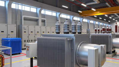
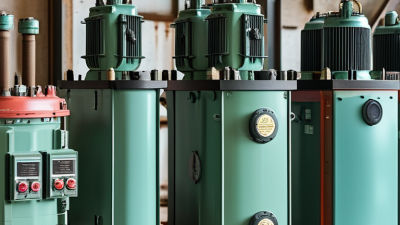
An electrical transformer transfers alternating-current power between circuits through electromagnetic induction. It usually changes voltage while keeping frequency constant. Its magnetic core guides flux, while primary and secondary windings carry input and output currents. Insulation separates the windings; a tank, cooling system, bushings, and protective devices support reliable operation. Small parts matter. Loose connections or degraded insulation can turn a routine load into a costly failure.

Transformer types serve different jobs. Power transformers support high-voltage transmission, while distribution transformers reduce voltage near homes, offices, and factories. Current and voltage instrument transformers provide scaled signals for meters and protective relays. Construction varies too: oil-immersed units use insulating fluid to remove heat, while dry-type units rely on air and solid insulation. An autotransformer shares a winding, saving material but providing no galvanic isolation. That trade-off is easy to overlook.

These choices matter as electricity networks expand. The International Energy Agency’s 2023 report, Electricity Grids and Secure Energy Transitions, estimates annual grid investment must rise from roughly $300 billion at the time of publication. It projects more than $600 billion annually by 2030. This is a system-wide estimate, not a transformer-only forecast, but it signals growing pressure on equipment planning. Engineers still need to assess load profiles, cooling, short-circuit strength, and site conditions; a catalog label cannot answer every field question.

Where Transformers Are Used in Modern Power Systems

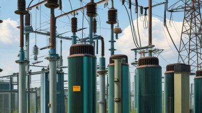
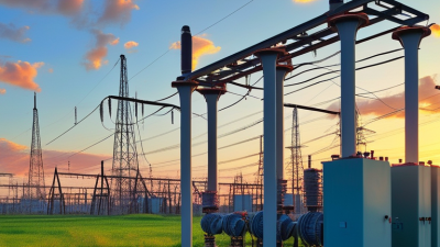
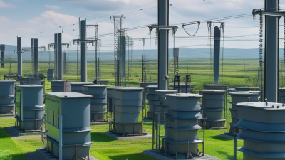
A transformer changes alternating-current voltage through electromagnetic induction, allowing power to move efficiently between parts of a grid. It does not generate electricity. At a power station, step-up transformers raise voltage for long-distance transmission, reducing current and limiting resistive losses in conductors. Near towns, substations use other transformers to lower voltage for local distribution.

The equipment is easy to overlook. A large unit may sit behind a substation fence, humming softly beside radiators that carry away heat. Smaller pole-mounted or ground-level units bring electricity closer to homes, workshops, and shops.

Transformers also connect wind and solar plants to transmission networks, while data centers and factories rely on them to match incoming voltage to equipment needs. Some installations include tap changers that adjust voltage as demand shifts. Not quite automatic everywhere. Operators still monitor temperatures, loading, insulation condition, and unusual sounds; a simple diagram rarely shows those constraints. Modern grids also carry power from more varied sources, so engineers must assess changing flows and equipment limits rather than assume electricity moves in one direction. A transformer is a familiar device, but its correct selection and maintenance depend on the actual site.

How Electrical Transformers Differ from AI Transformers

An electrical transformer and an AI transformer share a name, not a job. The electrical device transfers alternating-current energy between circuits through electromagnetic induction. It raises or lowers voltage, helping power travel efficiently through the grid and arrive at equipment at a usable level. In a substation, the clues are physical: a heavy steel tank, insulated windings, cooling surfaces, and high-voltage connections. The shared name still trips people up.

An AI transformer is a neural-network architecture. It processes tokens, such as words, by using attention to weigh how parts of a sequence relate. It does not change voltage or deliver electricity.

The technical distinction matters as AI expands: the International Energy Agency’s Electricity 2024 report estimates data-centre electricity use could rise from about 460 terawatt-hours in 2022 to 620–1,050 terawatt-hours by 2026. That range covers data centres broadly, not AI alone. A power transformer may serve a data centre, while an AI transformer runs as software on computing hardware.

Different jobs. Different physics. And there is a useful wrinkle: AI systems still depend on electrical transformers somewhere in their power supply, even though the model itself contains none.