Leave Your Message

How to Choose Electrical Switchgear in 2026?

Choosing Electrical Switchgear in 2026 requires more than comparing prices and catalog ratings. A reliable decision begins with the installation’s real conditions, not a generic product list. Record voltage, fault current, load patterns, ambient temperature, humidity, and available maintenance space. A switchboard beside a dusty production line needs different protection from equipment installed in a clean commercial room.

Recent projects show how easily assumptions can fail. Details matter. A designer may select a correctly rated assembly, yet overlook future solar generation, battery storage, harmonics, or limited outage time. These factors can change protection settings, busbar requirements, communication needs, and service access. Not always.

This guide explains how to assess Electrical Switchgear through safety, performance, maintainability, and lifecycle value. It considers low-voltage and medium-voltage applications, including circuit breakers, disconnectors, protective relays, metering, arc-flash mitigation, and remote monitoring. Technical decisions should align with applicable standards, manufacturer documentation, and local electrical regulations. Independent verification remains important.

In practice, the strongest choice is rarely the cheapest enclosure or the most advanced digital feature. It is the solution that matches the fault level, operating environment, expansion plan, and competence of the maintenance team. A factory with limited shutdown windows may value withdrawable breakers and condition monitoring. A small facility may need simpler equipment with clearer testing procedures.

Some recommendations will remain conditional. Data quality can be incomplete. Budgets can shift. Good engineering acknowledges these limits and documents them before procurement. That discipline supports safer installations, clearer accountability, and more dependable performance throughout the switchgear’s service life.
How to Choose Electrical Switchgear in 2026?

Define Electrical Switchgear and Its Role in Modern Power Systems

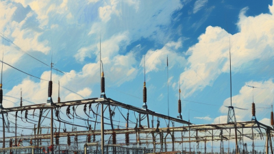
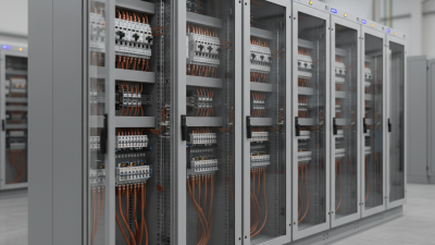
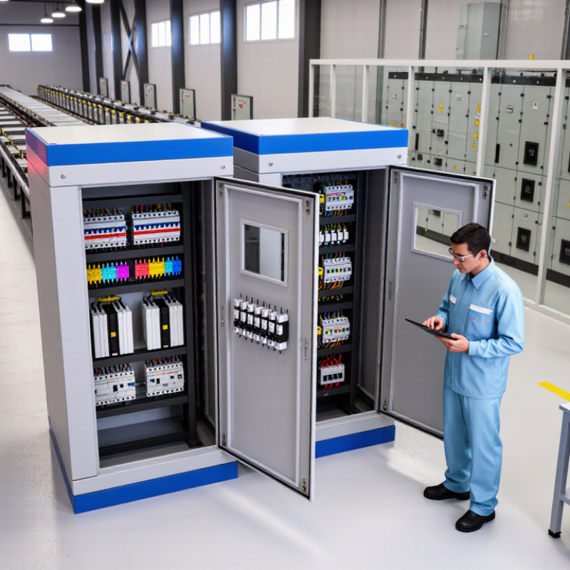
Electrical switchgear is an engineered assembly that controls, protects, and isolates electrical circuits. It may include circuit breakers, disconnect switches, fuses, busbars, relays, and measurement devices. These parts work inside a secure enclosure, often near transformers or main distribution panels.

Its role is practical and protective. During normal operation, switchgear directs power to buildings, factories, data centers, and infrastructure. When a short circuit occurs, protective devices detect abnormal current and interrupt the fault. Isolation switches then create a visible separation for maintenance. This reduces injury risks and limits damage to cables, transformers, and connected equipment.

Selection in 2026 requires more than checking voltage and current ratings. Engineers should examine fault levels, load patterns, enclosure protection, temperature, humidity, and available maintenance space. Digital sensors can support condition monitoring, but they do not replace sound protection coordination. That assumption can fail.

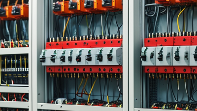
Field inspections often reveal loose connections, poor labeling, or cramped cable routes. Small details matter. A switchgear lineup may meet its catalog rating yet perform poorly in an unsuitable room. Arc-flash reduction, remote operation, and reliable communication interfaces deserve careful review. However, extra features can increase complexity and maintenance demands. The best design matches the power system, operating staff, and emergency procedures rather than chasing every new function. Specification documents should also state testing requirements, spare capacity, and acceptable performance limits clearly.
Assess Voltage, Current, Fault-Level, and Environmental Requirements

How to Choose Electrical Switchgear in 2026?

Choosing switchgear in 2026 starts with four numbers: voltage, current, fault level, and site conditions. The IEA Electricity 2024 report projects global electricity demand to grow by about 4% annually through 2026. That growth can expose weak capacity assumptions. Confirm the nominal voltage, highest system voltage, insulation level, and expected transient overvoltage. Then calculate continuous current, starting current, harmonics, and future load expansion. A panel rated only for today may become a costly limitation. Small detail, large consequence.

Fault level requires more than reading the transformer nameplate. Use utility data and IEC 60909 calculations to determine prospective short-circuit current. Check both the short-time withstand rating and the peak withstand rating. Circuit breakers also need suitable interrupting capacity, operating duty, and protection coordination. IEEE 1584-2018 supports incident-energy assessment, especially where maintenance staff may work near energized equipment. Uptime Institute’s Annual Outage Analysis 2024 continues to identify power-related failures among major data-center outage causes. That evidence supports careful protection studies, not optimistic estimates.

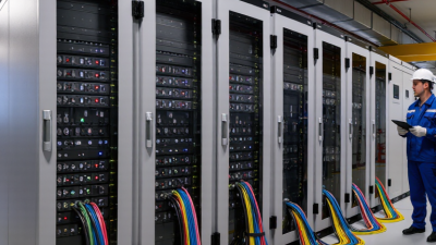
Environmental requirements often decide whether a design survives. IEC 62271-1 treats 1,000 meters as the normal altitude limit, so higher installations may require derating. Assess ambient temperature, humidity, condensation, dust, salt, corrosion, seismic movement, and indoor ventilation. An IP rating alone cannot solve poor drainage or heat buildup. In field reviews, the spreadsheet is usually neat. The assumptions are not. Recheck them with measured site data, maintenance access, and credible future loads.

How to Choose Electrical Switchgear in 2026? - Assess Voltage, Current, Fault-Level, and Environmental Requirements

Use this data table as a preliminary selection guide. Final equipment ratings must be verified against the applicable installation standard, utility requirements, protection study, manufacturer-tested configuration, and local electrical code.

Application / System Class Nominal Voltage Range Typical Rated Current Typical Short-Circuit Rating Recommended Equipment Configuration Key Protection Functions Environmental Requirements Selection Priority
Low-voltage distribution Up to 1 kV AC 250–4,000 A 25–100 kA for 1 second, depending on the installation fault level Metal-enclosed assembly with molded-case or air circuit breakers, busbar system, metering, and outgoing feeders Overload, short-circuit, earth-fault, undervoltage, and selective coordination Confirm enclosure IP rating, internal temperature rise, condensation control, pollution level, and cable-entry arrangement Fault level and coordination
Medium-voltage industrial distribution 1–17.5 kV AC 630–2,500 A 16–31.5 kA for 1–3 seconds Metal-enclosed switchgear with vacuum circuit breakers, load-break switches, current transformers, and voltage transformers Overcurrent, earth-fault, directional overcurrent, undervoltage, and transformer protection Assess indoor or outdoor installation, altitude, humidity, dust, corrosive gases, and access for maintenance Insulation level and arc safety
Medium-voltage utility feeder 12–36 kV AC 630–2,000 A 20–31.5 kA for 1–3 seconds Withdrawable or fixed circuit-breaker panels with sectionalizing, remote control, protection relays, and SCADA interfaces Feeder overcurrent, sensitive earth-fault, autoreclosing, breaker failure, and busbar protection Verify utility requirements, outdoor enclosure performance, wildlife protection, pollution severity, and communication availability Reliability and remote operation
Transformer primary switchgear 3.3–36 kV AC 200–1,250 A 12.5–31.5 kA for 1–3 seconds Load-break switch with current-limiting fuses for smaller transformers, or circuit breaker with relay protection for larger units Transformer overload, short-circuit, earth-fault, restricted earth-fault, and inrush restraint Coordinate insulation, cable termination, transformer impedance, ventilation, fire separation, and oil containment where applicable Transformer coordination
Motor control center Up to 1 kV AC 400–4,000 A busbar; feeder ratings based on motor size 25–100 kA, subject to the calculated prospective fault current Withdrawable or fixed motor starters with circuit breakers, contactors, overload relays, soft starters, or variable-frequency drives Motor overload, locked rotor, phase loss, earth-fault, underload, thermal capacity, and emergency stop Control heat dissipation, harmonics from drives, vibration, dust, moisture, ingress protection, and maintenance access Motor duty and maintainability
Critical power distribution Up to 1 kV AC 400–6,300 A 50–100 kA for high-capacity systems, subject to the fault study Form-segregated switchboard with automatic transfer, bypass arrangements, metering, and redundant incomers where required Short-circuit, earth-fault, under/overvoltage, frequency, synchronization, and transfer interlocking Specify continuous-duty temperature rise, fire rating, battery-room conditions, generator harmonics, and dual-power segregation Continuity of service
Renewable-energy collector system Up to 36 kV AC; DC ratings may also apply on the source side 630–2,500 A AC collector bus 16–31.5 kA AC, with DC fault-current assessment where applicable Compact metal-enclosed switchgear with feeder breakers, surge arresters, protection relays, and monitoring interfaces Overcurrent, earth-fault, anti-islanding, reverse power, voltage, frequency, and transformer protection Evaluate solar heating, wind-driven dust, humidity, salt mist, altitude, outdoor UV exposure, and communication resilience Environmental durability and grid compliance
High-voltage transmission or substation equipment Above 52 kV AC 1,250–4,000 A 31.5–63 kA, commonly specified with a 1–3 second short-time withstand period Air-insulated, gas-insulated, or hybrid equipment selected according to space, accessibility, insulation, and maintenance requirements Distance, differential, overcurrent, earth-fault, breaker failure, autoreclosing, and synchronism check Assess lightning and switching impulse levels, altitude correction, seismic duty, pollution, wind, ice, and electromagnetic compatibility Insulation coordination and system stability
Hazardous or corrosive location Determined by the connected electrical system Based on calculated load current and continuous-duty heating Based on the prospective fault current at the installation point Certified enclosure and switching equipment suitable for the classified hazardous area and gas, vapor, dust, or chemical exposure Short-circuit, earth-fault, overload, emergency isolation, and area-specific interlocking Confirm hazardous-area classification, gas or dust group, temperature class, corrosion category, IP rating, and surface-temperature limits Safety certification
High-altitude installation Any system voltage Use the calculated load current; verify cooling derating Use the calculated fault current; verify dielectric and thermal derating Standard switchgear may require altitude-adjusted insulation clearances, cooling design, or a higher-rated assembly Protection settings must reflect the network study and equipment thermal limits Above 1,000 m, check manufacturer altitude correction for insulation, current-carrying capacity, cooling, and interrupting performance Derating verification
Technical checkpoints: Confirm the maximum operating voltage, basic insulation level, continuous current, short-time withstand current, peak withstand current, short-circuit breaking current, protection-clearing time, enclosure classification, internal arc requirements, temperature range, altitude, seismic conditions, pollution level, and required service continuity before issuing the final specification.

Compare Switchgear Types, Insulation Methods, and Protection Features

Choosing electrical switchgear in 2026 starts with the installation, not a catalog. Metal-enclosed switchgear suits medium-voltage distribution and protects energized parts from accidental contact. Air-insulated designs are easier to inspect and often simpler to repair. Gas-insulated equipment saves floor space, especially in dense substations, but requires careful leak monitoring and specialist servicing. Solid insulation can reduce exposed gaps and improve compactness, yet thermal aging deserves close attention. Field reviews often reveal failures because engineers compare dimensions before fault levels.

Insulation selection should match voltage, altitude, humidity, pollution, and maintenance access. At a coastal site, salt deposits can weaken surface performance. In dusty workshops, creepage distance may matter more than compact dimensions. Air insulation needs clearances; gas and solid systems need verified dielectric coordination. Ask for routine-test records, temperature-rise data, and short-circuit withstand ratings. Do not accept “maintenance-free” as a complete engineering statement. It rarely is.

Protection features should match the actual network. Vacuum circuit breakers handle frequent switching and interrupt fault current without oil. Current transformers, relays, and trip coils must coordinate with upstream and downstream devices. Arc-resistant construction can direct hot gases away from operators, but only when installed as tested. Interlocking prevents unsafe switching sequences, while earth-fault, overcurrent, undervoltage, and busbar protection address different risks. Digital monitoring adds alarms for temperature, partial discharge, and breaker wear. It can also create false confidence if sensors are poorly calibrated. Review local standards, maintenance skills, spare parts, and emergency access before approving the final design.

Evaluate Safety Standards, Digital Functions, Maintenance, and Expandability

How to Choose Electrical Switchgear in 2026?

Selecting switchgear starts with verified safety, not a glossy specification sheet. Check compliance with applicable IEC standards and local electrical codes. Confirm rated voltage, short-circuit withstand, insulation level, and internal arc classification. I would also review test certificates from an independent laboratory. A project I once assessed had adequate current capacity but insufficient clearance for actual cable bending. The paperwork looked fine. The installation did not.

Digital functions should support decisions, not create noise. Useful systems measure current, voltage, temperature, power quality, and breaker status. Remote alerts can identify an overheating connection before an outage occurs. However, sensors require calibration, secure networks, and trained users. Cybersecurity matters too. Disable unnecessary access, separate control networks, and record firmware changes. More data is not automatically better.

Maintenance planning should influence the purchase. Choose accessible compartments, clear labels, test points, and replaceable components. Infrared inspections and torque checks can reveal loose connections, but they cannot replace qualified inspections. Ask how long critical parts remain available. Also examine the expansion path. Spare cubicles, reserved busbar capacity, extra cable space, and room for future protection devices can reduce later disruption. Be realistic about forecasts. Loads change, and optimistic expansion plans often become expensive unused space. No switchgear is truly maintenance-free.

Select Suppliers, Verify Total Cost, and Plan Installation Requirements

How to Choose Electrical Switchgear in 2026?

In 2026, switchgear selection should begin with the supplier, not the catalog. Ask for current test certificates, manufacturing controls, warranty terms, and documented field references. Request records from projects with similar voltage, fault levels, climate, and operating cycles. Inspect how the supplier handles design changes, spare parts, and technical questions. Fast replies matter, but traceable answers matter more. Check competence. An impressive presentation cannot replace independent verification.

Compare total cost across the equipment’s full service life. Include engineering, protection studies, transport, storage, installation, testing, training, energy losses, maintenance, and disposal. Ask whether quoted accessories are essential or merely convenient. Clarify exclusions before approval. One low bid may become expensive after site changes and delayed commissioning. Use a written cost model. Keep assumptions visible. Even experienced teams miss small items.

Installation planning should start during specification. Confirm room dimensions, lifting paths, floor loading, cable entry, ventilation, and working clearances. Review arc-flash boundaries, grounding, interlocks, and emergency access with qualified professionals. Check site conditions, including dust, moisture, altitude, vibration, and temperature. Schedule factory and site acceptance tests with named responsibilities. Allow time for protection settings and commissioning records. On one project, a cable route looked adequate on paper but blocked maintenance access. That mistake was preventable. Walk the route physically.