What Are the Top 3 Phase Transformer Winding Types in 2026?
In 2026, choosing a three-phase transformer winding connection remains a practical decision, not a branding exercise. The 3 Phase Transformer Winding arrangement influences voltage relationships, neutral availability, grounding behavior, and response to unbalanced loads. A diagram may look simple. The consequences are not.
This guide examines three widely used configurations: star (wye), delta, and zigzag. Star connections can provide a neutral point and support line-to-neutral loads when the system design allows it. Delta connections often handle certain load imbalances effectively and can provide a path for circulating triplen harmonics. Zigzag windings are commonly selected for grounding and neutral-support applications, though their suitability depends on the network and equipment ratings. None is universally best. Details matter.
The right choice starts with the application. Check primary and secondary voltages, load profile, grounding method, harmonic conditions, fault levels, and the transformer nameplate or design data. For example, a facility with many single-phase loads may value a stable neutral, while an industrial feeder may prioritize other characteristics. Installation conditions matter, too. A connection that works well on paper may need reconsideration after site measurements reveal unexpected imbalance. This overview compares operating principles, strengths, limitations, and common uses for each type. It is a starting point, not a substitute for engineering review. Even familiar diagrams can hide important assumptions. Confirm the required vector group and protection settings with qualified personnel before specifying equipment.
How Three-Phase Transformer Winding Connections Are Classified
What Are the Top 3 Phase Transformer Winding Types in 2026?
How Three-Phase Transformer Winding Connections Are Classified
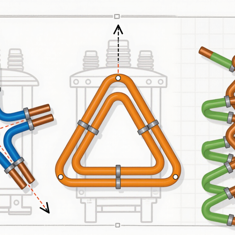
Three-phase transformer windings are commonly classified by how their three coils connect: star (Y), delta (Δ), or zigzag (Z). These are connection types, not a quality ranking. In a star connection, one end of each phase winding meets at a neutral point. This can support a neutral conductor and provide two useful voltage levels. Delta connects the coils end to end in a closed loop. It has no neutral point, and its loop can help handle certain unbalanced loads. Zigzag uses interconnected coil sections to create a neutral and manage some grounding conditions. Details matter.
Engineers also classify a transformer by its primary-to-secondary connection and phase displacement. IEC 60076-1 uses vector-group notation: letters identify winding connections, while a clock number indicates phase shift. For example, Dyn11 describes a delta high-voltage winding, a star low-voltage winding with neutral, and a 30-degree displacement. The marking is useful, but it does not replace checking the nameplate and system requirements. An overlooked neutral or mismatched phase shift can complicate parallel operation. The International Energy Agency’s Electricity Grids and Secure Energy Transitions (2023) says annual grid investment needs to exceed USD 600 billion by 2030 in its climate-aligned pathway. That wider grid build-out makes clear, consistent connection classification increasingly important. Yet field conditions can still expose assumptions that looked tidy on paper.
Three Common Three-Phase Transformer Winding Connections
Typical absolute phase displacement between primary and secondary line voltages. Values shown are representative; the transformer’s vector group and winding polarity determine the exact displacement.
Delta-wye and wye-delta connections commonly have a 30° displacement, while a correctly polarized wye-wye connection commonly has 0°. These are connection examples, not a popularity ranking.
What Defines a Delta-Connected Winding
What Defines a Delta-Connected Winding
A delta connection is a closed triangle. The end of each phase winding connects to the start of the next, creating three junctions for the supply lines. There is no winding neutral point. In a balanced system, each winding sees the line-to-line voltage, and line current is about 1.732 times winding current. For example, a measurement between two line terminals reflects the voltage across one winding.
This closed loop can provide a path for certain triplen harmonic currents, limiting their appearance in line voltage. However, circulating currents may add heat, especially with nonlinear loads or inadequate cooling. Delta windings also lack an accessible neutral for ordinary phase-to-neutral loads. The triangle looks simple on a diagram, but real installations depend on correct polarity, vector group, grounding, and protection settings.
Tips: Check the transformer’s connection diagram and vector group before energizing it. Confirm winding polarity and protective-device settings with qualified personnel. If the load is unbalanced or harmonic-rich, review the expected heating; a delta connection is not automatically the best choice.
How a Wye-Connected Winding Provides a Neutral Point
In a three-phase transformer, a wye-connected winding joins one end of each phase coil at a shared point. That junction can provide a neutral conductor for phase-to-neutral loads, such as lighting or small equipment in a four-wire distribution system. On a balanced system, phase-to-neutral voltage is about 0.577 times phase-to-phase voltage. For example, a 400-volt line voltage gives roughly 230 volts phase to neutral. That matters. But a neutral is not automatically available: the connection must be brought out, and the grounding arrangement must suit the installation.
The International Energy Agency’s Electricity Grids and Secure Energy Transitions report says about 80 million kilometres of grid need to be added or refurbished by 2040. That expansion makes adaptable distribution designs important, though the figure is not a comparison of transformer winding types. In practice, a wye neutral can help supply mixed single-phase and three-phase loads and provide a reference for grounding. Its behaviour under unbalanced loading depends on the transformer design and neutral grounding; engineers should check the nameplate vector group and system drawings. A small detail, easily missed: an ungrounded or inaccessible star point may not serve as a usable neutral.
Why Zigzag Windings Support Grounding and Load Balance
In 2026, three-phase transformer designs commonly include delta, wye, and zigzag windings. Zigzag windings are especially useful when a system needs a neutral point for grounding. Their interconnected coil sections create a path for zero-sequence current during a line-to-ground fault. That path lets grounding equipment and protection devices respond to faults in a controlled way. The exact current depends on the winding design and grounding impedance.
Zigzag transformers can also help support phase-to-neutral voltage when single-phase loads are uneven. Picture a workshop where lighting and small tools draw more current from one phase than another. A properly selected zigzag unit may reduce voltage imbalance, but it cannot correct every overloaded feeder. Engineers still need to check load measurements, transformer impedance, grounding method, and protection settings. It is easy to overstate the benefit; actual performance depends on the whole installation.
Tips: Record phase currents and neutral-to-ground voltage under typical operating conditions. Confirm the required fault-current limit before sizing the transformer. A zigzag winding is a tool, not a substitute for sound load planning.
How to Compare Delta, Wye, and Zigzag Connections in 2026
In 2026, comparing delta, wye, and zigzag transformer connections starts with the load and grounding needs.
Delta connects three windings in a closed loop and suits many three-phase loads that do not need a neutral. It can provide a path for circulating triplen harmonic currents, but it may not supply a neutral directly.
Wye joins one end of each winding at a shared neutral point. That point can support line-to-neutral loads when the system design includes suitable grounding.
Neutral access matters.
Zigzag uses interconnected winding sections to create a neutral, often where a distribution system needs grounding support. It can also help manage certain unbalanced conditions, depending on the transformer design and network.
That is its specialty.
Unlike a basic delta or wye arrangement, zigzag is commonly selected for a specific system function rather than as a general-purpose connection.
Compare the three against voltage, load balance, grounding, fault behavior, and harmonic levels. A delta-wye transformer may suit systems needing a neutral on the wye side, while a delta-delta arrangement can fit loads without one. These are not automatic rules. Actual performance depends on winding design, protection settings, and the connected equipment. Check the transformer nameplate and wiring diagram, then confirm the choice with a qualified engineer.
I would not choose by connection name alone; that shortcut is tempting, but it can miss a system’s real constraints.